Modeling geometry using X Y maytrix from Matlab

Previous Topic Next Topic
 
classic Classic list List threaded Threaded
5 messages Options
Reply | Threaded
Open this post in threaded view
|

Modeling geometry using X Y maytrix from Matlab

Philippe Thomas
Working with Matlab environment to generate cambered plate profile, I was looking forward importing these X Y variable to generate the 2D shape, and ultimately run cfd simulation. I was able to import the spline using a csv file where the date are stored, but cannot close the contour line and generate a 2D shape.
The  NACA profile menu generates the shape via a dedicated program.
Any suggestion to address the case.
Thanks in advance.
Reply | Threaded
Open this post in threaded view
|

Re: Modeling geometry using X Y maytrix from Matlab

Precise Simulation
Administrator
Could you attach some example data from which you want to generate a shape which results in issues?
Reply | Threaded
Open this post in threaded view
|

Re: Modeling geometry using X Y maytrix from Matlab

Philippe Thomas
Thanks for reply. Being new to CFDtool, I did not find the solution straight away. With my csv file, as attached, using Polygon load data, I was able to create the complete foil shape.
Cambered_foil_profile

The main difference with the NACA profile program is the boundary format. In my case multiple segments, with the NACA generation profile 2 segments 1 for intrados, 1 for extrados) which makes it easier to compute function like the pressure coeffcient.

Thanks


Reply | Threaded
Open this post in threaded view
|

Re: Modeling geometry using X Y maytrix from Matlab

Precise Simulation
Administrator
It technically should be able to create a single spline/bezier curve from a series of points. If you upload the CSV data I can have a look.

Reply | Threaded
Open this post in threaded view
|

Re: Modeling geometry using X Y maytrix from Matlab

Philippe Thomas
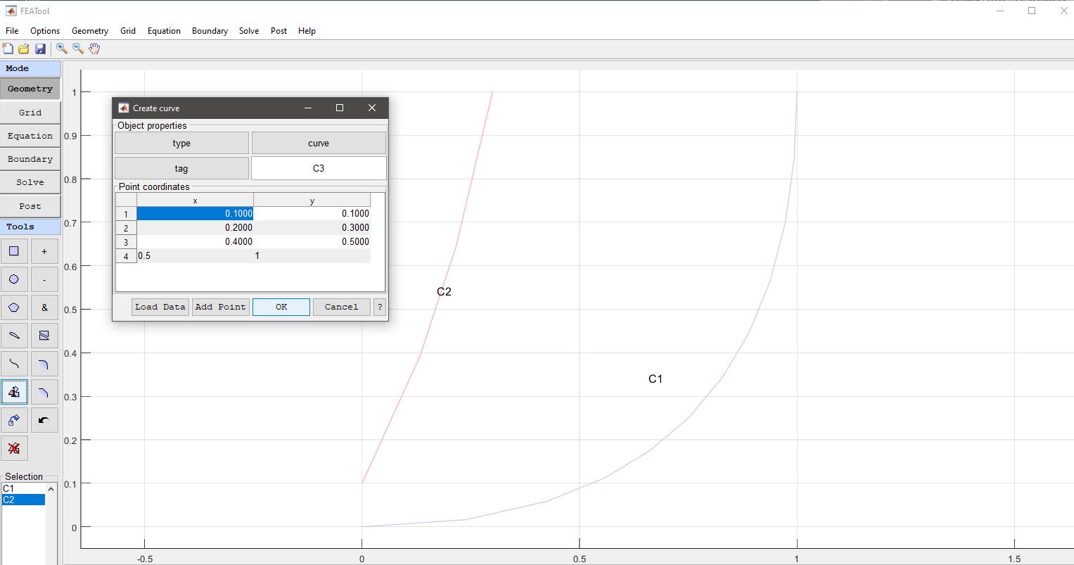
Thanks for the hints on loading data from "csv" file with spline function.
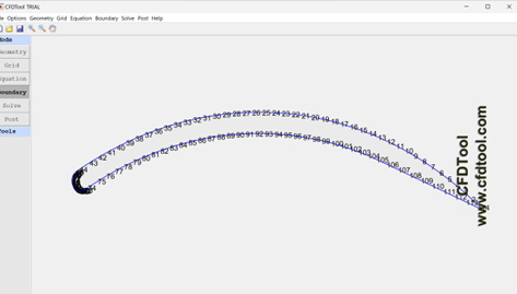
I was able to generate the profile and test run using Navier Stokes equation, with turbulent boundary layer (Re=1E6). I have attached some images.


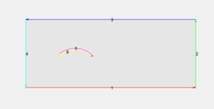
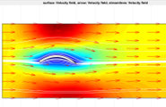
Going forward, I would want to check drag and lift coefficient with respect to available data from airfoil database. I used the tutorial on the flow around the cylinder, with the calculation of the lift coefficient.

Equation for the local drag force is set to : nx*p+miu*(-2*nx*ux-ny*(uy+vx))

Is there any reference documentation, apart from the tutorial, to explain the construction of this parametric equation from the integral equation ?

I set the equation for the local lift force to : ny*p+miu*(-2*ny*uy-nx*(ux+vy)) but want to check the correctness.

The combination with Matlab capacities makes CFD / FETools very powerfull.

Thanks for the support