Model reverse engineering tool


|
This post was updated on .
I don't take very good notes when building anything but the simplest models. Case in point: I recently returned to a human-oid model I had worked on earlier and realized I needed to know the parameters of the geometric operations that I had used so that I could finish it off with the hands and feet.
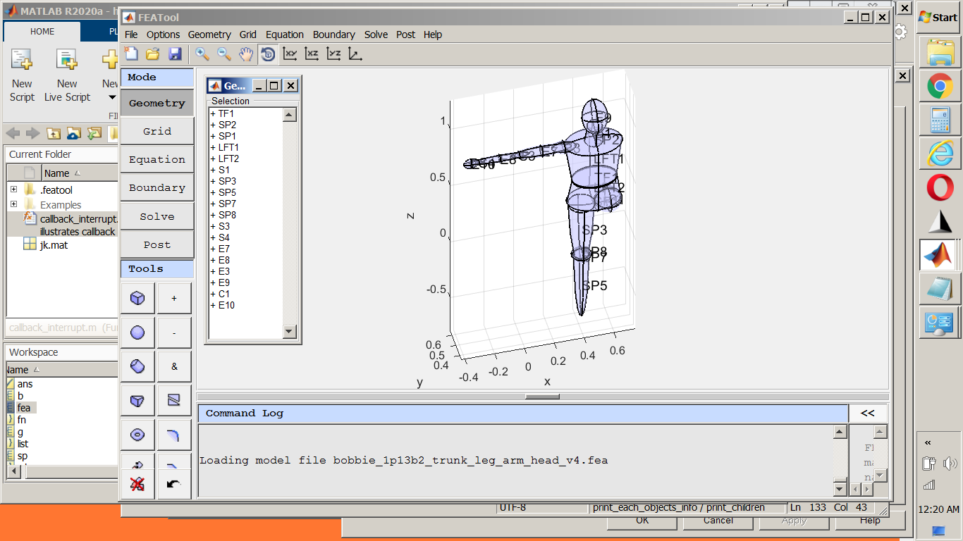 Much of the information can be obtained piece-by-piece using the "Inspect" tool, such as that for primitive created objects such as S4: 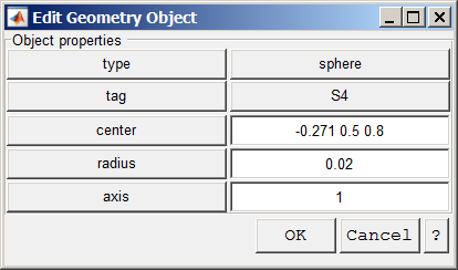 But wanting more of a 'complete' list, I decided to see what I could uncover from the fea.geom and began writing a script to 'dump' all the construction related information I could find: "print_geom_objects (GEOM, taglist [optional])"; print_geom_objects.m [There is an updated version of the script below in my post dated Oct 25, 2020.] I realize this tool breaks with a future FEATool build, but it does give me most of what I think I would want to see and I can hopefully maintain it if it turns out to be as useful as I think it might. As you have time, I'd appreciate any comments you may have. I have a few specific questions that I have included below: 1. For a 'transformed' type, what is the meaning of the param{6}?
 1:  'TF2', 'transformed'
       disp:   0.000000  0.100000  0.000000
      scale:   2.500000  2.500000  1.000000
    rotnAng:   0.000000
   rotnCntr:   1.000000  0.000000  0.000000
   rotnAxis:   0.000021  0.000018  0.000500
      p6(?):   1.000000
2. Same question for the 'v' struct member for the type 'point'.
 5:  'P1', 'point'
   center:  0.000000   0.000000   0.000000
        v:  0.000000   0.000000   0.000000  (?)
3. For the type 'extrusion' there seem to be multiple uses for param{3}. I have tried to deal with it by identifying an extrusion done in a 2D Workplane and one done from the face of an object. Did I get this right? Is there more information such as the tag of the object whose face was extruded?
        if isstruct(obj.param{3}) && ...
           isequal(fieldnames(obj.param{3}),[{'p'}; {'n'}; {'t'}])
            %  extrusion from 2D Workplane at:
            fprintf ("   %sWkPpoint: %9f  %9f  %9f\n", space, obj.param{3}.p);
            fprintf ("   %sWkPVnorm: %9f  %9f  %9f\n", space, obj.param{3}.n);
            fprintf ("   %sWkPVtang: %9f  %9f  %9f\n", space, obj.param{3}.t);

        else  % if isinteger(obj.param{3}) but it is a FLOAT?
            fprintf ("   %sobj face:  %d\n", space, obj.param{3});
4. Type 'brep' (not sure what that stands for) seems to used for an object that was created when its 'child' was split using "Split Object(s)". Is this correct?
       Gen 2
       1:  'SP2', 'brep'
           cutplane pt:   0.500000  0.500000  0.500000
         cutplane norm:   0.000000  0.000000  1.000000
          Gen 3
          1:  'B1', 'block'
                    min        max
             x:  0.000000   1.000000
             y:  0.000000   1.000000
             z:  0.000000   1.000000
This is a work in progress as you can see - some types are only output by tag. Thanks in advance for any comments you are able to provide! Kind regards, -Randal |
Re: Model reverse engineering tool
|
Administrator
|
Thank you for sharing the serialization script, that can indeed be very useful. Looking at your "after shark attack" model, (jokes aside if one can get away with any form of symmetry one can save significant simulation time/memory), I see that I should probably try to add functionality to customize labels/tags and possibly groupings (without needing to join/merge objects). As for your questions
That should be a logical/boolean indicating if the rotation angle is given in degrees or not (if not then it should be in radians). https://www.featool.com/doc/geom__apply__transformation_8m.html The "v" field is always the vertices of the object defined as the points where edges coincide (and edges as the lines where faces intersect). For consistency the point object is given a "v" field as well with its point coordinate. The "gobj.param" field is technically not really used anymore but still around for historic reasons, and I tend to put the operation parameters there just in case they would be needed. For the extrude operation the following properties are stored gobj.param = {d, v, face_wpl}; as briefly described in https://www.featool.com/doc/gobj__extrude_8m.html so for 3D objects is is an integer indicating the face to extrude (although Matlab per default represents all numbers as doubles). I guess I forgot to change to a more descriptive name. The "type" field is just used to discern between geometry object primitives (block, cylinder etc.) and more complex types. In this case "brep" just refers to the underlying OpenCascade BREP (Boundary Representation) CAD format that is used to describe the object (as its native to the geometry engine, in contrast to for example STEP or IGES). The CAD format is specified in the "data_type" field with the actual CAD data in the "data" field. |
|
|
You are quite welcome. As I refine it I will try to update this post with later versions. As for the "after shark attack" :-),thanks for the laugh! Actually once I get limbs completed, I plan to recreate or duplicate their mates Thanks for the answers and elaboration regarding my questions. Glad you kept the param field going, clearly it is providing me (the reverse engineering script) what is needed. Any chance the object whose face was extruded is in there somewhere? This is not necessary since it can be observed by looking at the model. Again, thanks for the interaction. Kind regards, Randal |
Re: Model reverse engineering tool
|
Administrator
|
This post was updated on .
Considering that the more complicated geometry is the more involved and difficult the meshing becomes (and especially anisotropic as I think it is why your previous squished and filleted ellipse has issues meshing) and may not lead to significantly increased accuracy. I'm not sure how accurate you need but I would consider if your really need lifelike tapered joints and such as it adds a lot of complexity (and work). I would start with just a cylinder for the torso and with smaller ones for the legs and arms and refine it from there if required. A quite inconvenient workaround would be to export the m-file commands and search/regexp it for the command (for example "extrude") with the input parameters of the input object you are looking for. If it hasn't been cleared the m-file commands are stored in the "fea.gui.log/mlog/modelcmdlog" fields (depending on version) as: load my_model.fea -mat fea.gui.log/mlog Unfortunatlely, the children field is removed for extrude/revolve objects so as to prevent the revert operation from working on these objects (as I thought it would be too confusing and maybe not make sense). I should probably have stored the tags of the parent objects though. |
|
|
I have made some changes and additions to "print_geom_objects". It should intercept all current object types. I have an "else" case to catch any new or modified types.
print_geom_objects.m Thanks for the analysis and suggestions ... based on my initial experiments, I am seeing that the current density (which is what determines skeletal muscle stimulation) varies with cross sectional area in some cases. And I want to try to show how this applies to various body parts. I understand (at least at an elementary level) what you are saying, and I will keep that in mind as I proceed. Hopefully, I will see that certain detail is quite unnecessary and can simplify. The chamfer & fillet I was trying to use to "sharpen" the propeller blade, I am hoping to find are not that important as I would be using the prop as a current source, rather than being interested in the fields inside it ... Perhaps I ill find that a plate or a sphere of the proper size will do about as well... But are you saying that the ellipsoids I am using to make the humanoid are much more complex (more difficult to mesh and requires many more cells) than cylinders? What about a cone vs a cylinder? I DO believe that I could do a great deal with cones and lofts and hemi-spheres (for rounding) Are spheres more difficult, mesh wise, than ellipsoids? I realize that you may not be able to answer these questions generally (the devil is in the details :-). I would like to look into what you suggest here...although I am not quite clear on just where to look and what I might find... but let me try a few things first. If you do add these, I'd appreciate a heads-up so I can update the script. Kind regards, Randal |
«
Return to Technical Issues
|
1 view|%1 views
| Free forum by Nabble | Edit this page |