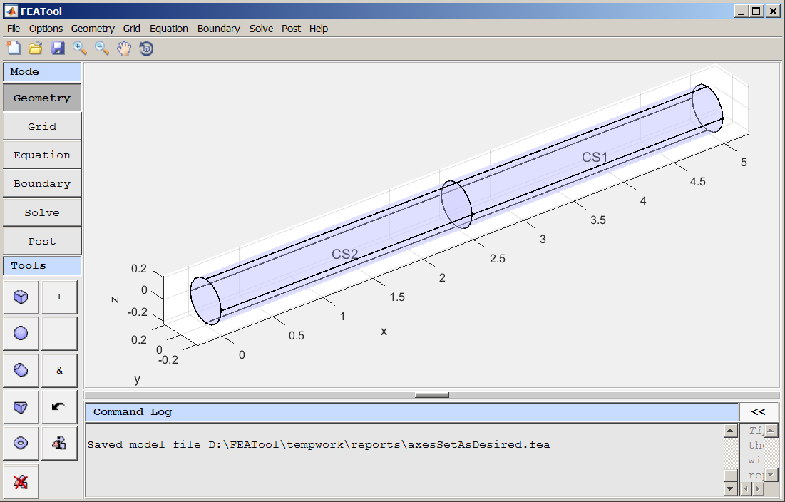
The model view below is of a 0.2 radius cylinder of length 5 that has been bisected using two enclosing boxes sharing a common face at the cylinder midpoint (x=2.5). The cylinder was duplicated in place and then B1 was subtracted from C1 and B2 subtracted from C2.
[BTW, I'd like a name for this method of internal boundary creation (or object bisection) ... "by duplication and subtraction of adjoining enclosing objects" ... or something... I expect to use it frequently.]

So far so good.
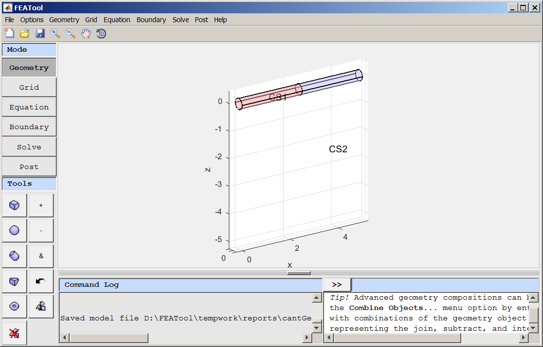
The problem is that somehow, I created the following "equivalent" model. But I do not recall the steps that I used. The problem is that I do not like the way the axes are located with respect to each other. I would prefer that plane containing the x- & y- axes would intersect the z-axis "at" or "near" the z extent (negative preferred in this case) of the object, e.g., at z=-0.2

Is there some way to recover from this state to one that displays the axes similarly to the first one? Is there some vestige of another object hidden from view that is driving the location of the axes?
Here is the "fea" file for the mis-behaved version :-)
cantGetAxesAsDesired.feaAny ideas will be greatly appreciated,
-Randal