With the release of version 1.13.1, I was able to build and gridgen the model pictured below: points at either end of a block.
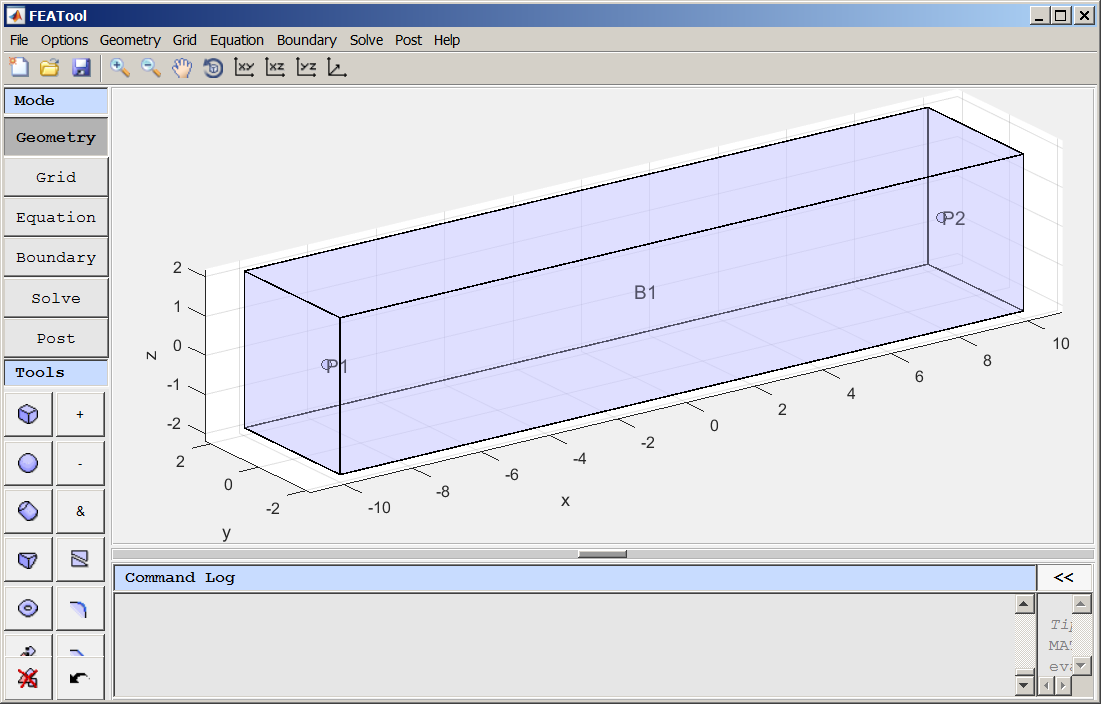
As I proceeded to complete the Equation and Boundary sections, I realized that I may not understand the use of a point source in a 3D conductivity model. 
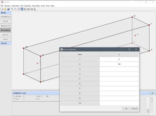
I had in mind that one point would be a current "source" with a fixed Voltage (e.g.,120V) and the other point would be the current "sink" source (set to 0V). However, when I selected the Boundary mode, I was only able to view the external boundaries. I could not figure out how to set the voltages on the source and sink points. 
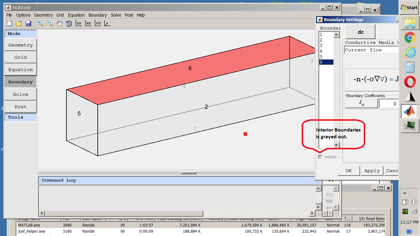
My first question is: can I do what I intened with FEATool using point source/sink to map a field in a tank of water? If not, how would the point be used in a 3D conductivity model? If so, then how do I set the voltages on the points? Here is the .fea model file: HowToSetInternalPointBoundary.fea Kind regards, Randal |
Administrator
|
First, just to clarify there is a significant difference between "point sources" (found in subdomain mode) and "point constraints" (in boundary mode). Sources (and sinks) add a forcing term to the selected points and modify the solution accordingly, but to constraint on the solution itself is prescribed. A "point constraint" in contrast does just what is says, explicitly set the value of the point to what has been prescribed.
The first would be analgous to pushing (or pulling) on a taut string with a force (your finger), while the second grabbing and holding the string in a fixed position. If everything works as it should you should have a "Point Constraint..." option in the "Boundary" menu, which opens a dialog box where you can prescribe fixed values for individual points |
This post was updated on .
Very kind of you to gently mention that I should read the menu :-) This is in fact what I was looking for, something to place a voltage difference between the points. However, your discussion/explanation leads me to question whether or not I should be using the "Point source" capability. After doing this model both ways, the point constraint method seems to give the type results I expect: that of a pair of electrodes with a constant voltage difference in a conductive medium (water). What I would like to do before I leave this, is to build this model using spheres and one using points (Point Constraints... from the Boundary menu) that, if possible, by adjusting the voltage and sphere size, to produce similar voltage plots...if this even makes sense. This seems like "Modeling and Simulation" topic, so I shall post it there ("Modeling DC conduction electrodes using Point vs. Sphere objects": http://forum.featool.com/Modeling-DC-conduction-electrodes-using-Point-vs-Sphere-objects-tp968.html ). Kind regards, Randal |
Free forum by Nabble | Edit this page |