Precise Simulation wrote
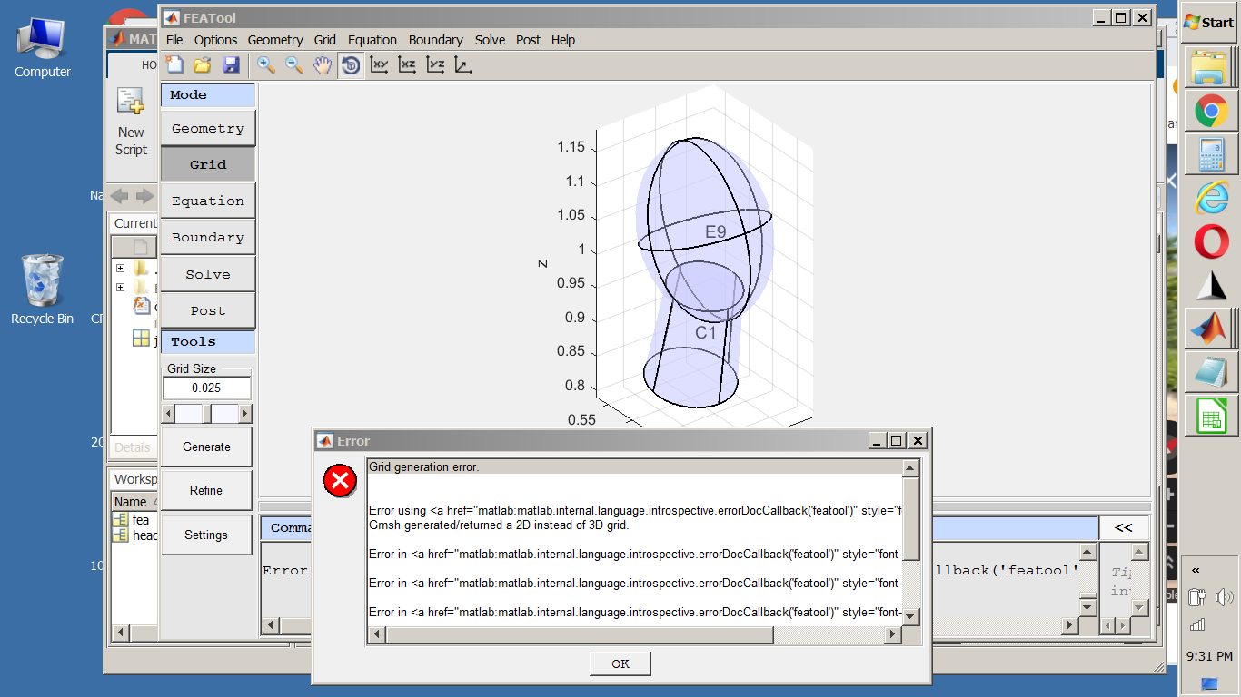
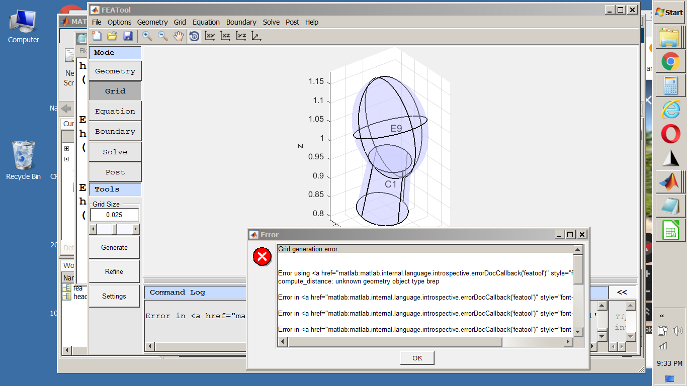
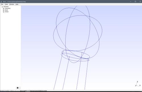
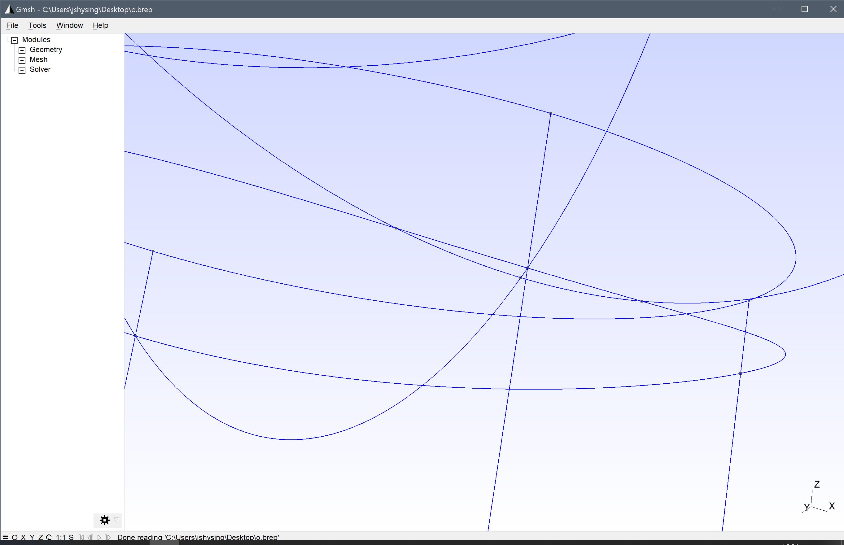
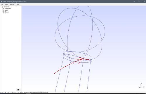
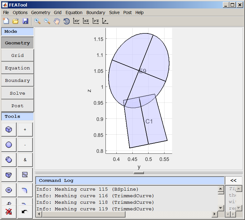
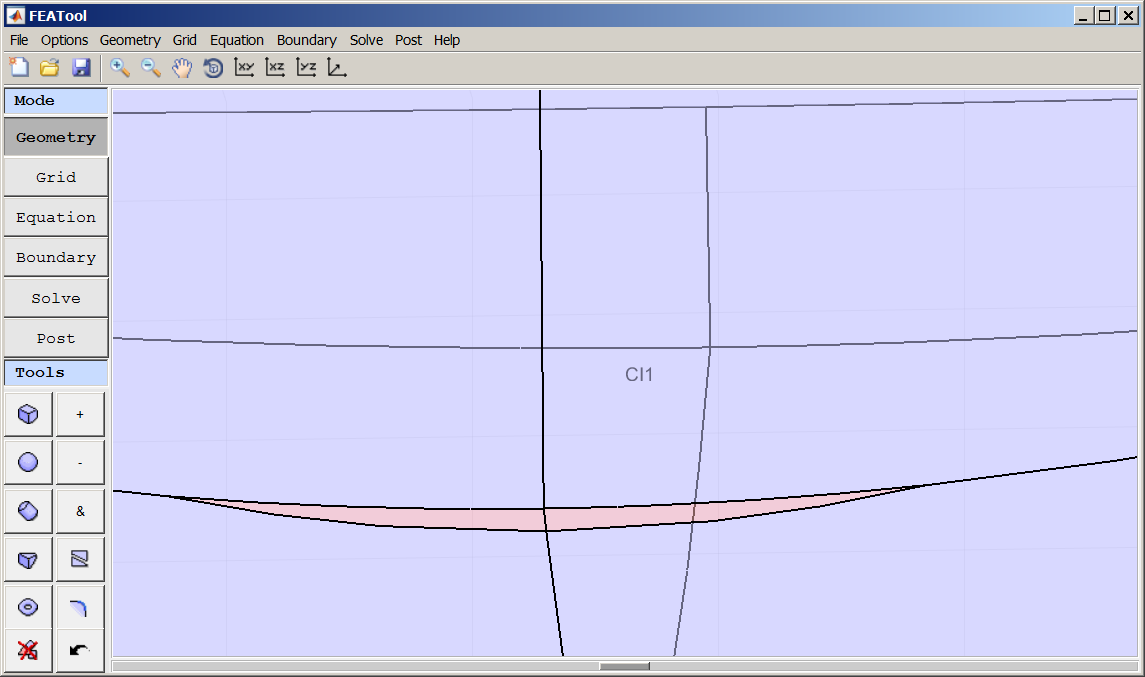
Before meshing all overlapping objects are decomposed into minimal regions, in this case this results in a very thin region which is hard to mesh
Thanks for taking the time to help me "see" this. I do understand - I can see that the overlapped volume is small, but it just does not seem to be that thin relative to the other volumes.
Precise Simulation wrote
I have unfortunately not been able to fix the geometry engine to automatically fix/merge this.
This I also understand. I am not hoping (or even asking for a fix/enhancement) I just want to be able to do the best with current capabilities.
Precise Simulation wrote
To avoid/minimize this issue you can try to merge geometry objects so that the number of overlapping regions is reduced or eliminated before meshing.
It sounds as if
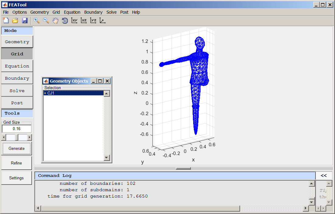
merging (joining, "+") geometry objects before meshing is a good general rule. For my use-case, since you have provided a convenient means for inserting slices/cut-planes to be used for integration, I do not see any downside to merging all components of the geometry for a "subject" model which is being suspended in water and through which current flow is to be analyzed. (I can always "undo" the merge if I want to make changes and then re-merge.)
Does this sound like a good general rule?I remain intrigued by the fact that the "head and neck" issue was also solved by creating a "plug and socket" version (which seems to me to have the same sharpness in the geometry, although no small regions - they all become part of the neck) by duplicating the neck and subtracting it from the head. (As I write this, I sense that I may be beginning to get a feel for the problem :-)
This brings me to what could be a great help in my use-case. When I mesh my overall problem in preparation for running the solver, whatever subject model(s) I have are all enclosed by a "body" of water. I have found that I do not have to "subtract" the subject model from the water to get a result. However, there are, of course, times when the meshing fails. I cannot merge the subject model(s) and the water because they all may have separate conductivity.
BUT would I get better (or more likely to succeed) mesh results if I made it a practice to modify the "water" component to contain "cut outs" of all the subject models by subtracting them from it?Thanks for the discussion and
Kind regards,
Randal